


News
Technology transforms the world · Integrity builds the future · Leading boundless possibilities
What are the basic architecture, salient features, and underlying principles of a trigger diode?
Category:
Release Date:
2025-05-09
Description
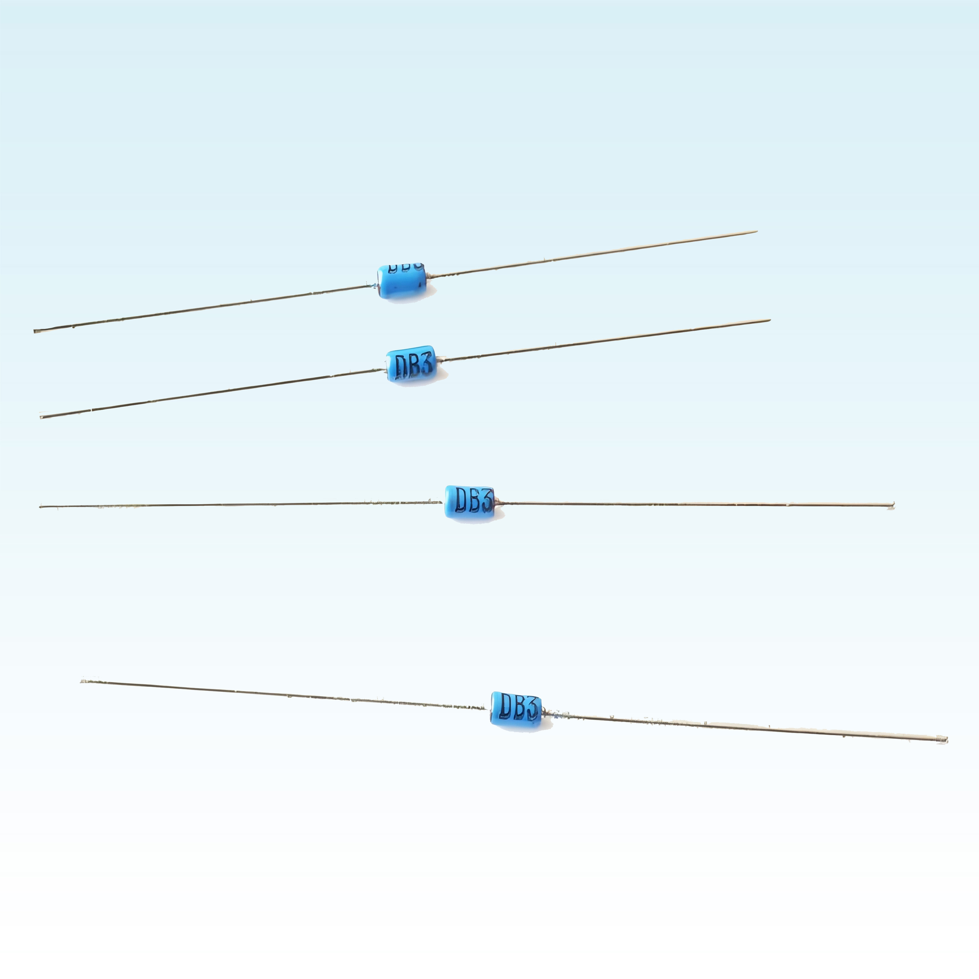
A trigger diode, also known as a DIAC, is a three-layer, symmetrical two-terminal semiconductor device. It is commonly used to trigger triacs and serves functions such as overvoltage protection in circuits.
I. Definition and Principle
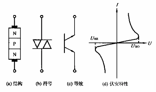
A trigger diode, also known as a thyristor or a bidirectional trigger diode (DIAC), is a two-terminal device made of semiconductor material that exhibits unidirectional conductivity. It comprises four regions—P, N, P, and N—such that the two adjacent N‑type regions form a PN junction, referred to as the control junction, while the other two P‑type regions form another PN junction, called the main junction. When a forward voltage is applied to the control junction, the PN junction breaks down, allowing current to flow through the trigger diode and completing the circuit. The trigger diode operates in the reverse breakdown state and, during manufacturing, is characterized by a low breakdown voltage with a stable reverse breakdown voltage.
II. Types
Types of trigger diodes include high‑voltage trigger diodes, low‑voltage trigger diodes, and bidirectional trigger diodes. These various types differ in parameters such as breakdown voltage and current rating, making them suitable for different application scenarios.

III. Characteristics
- Unidirectional conductivity: The trigger tube exhibits unidirectional conductivity, meaning current can flow only from the anode to the cathode and not in the reverse direction.
- Quick switch: The trigger tube features rapid switching speeds, enabling the circuit to be closed and opened within a short time.
- High reliability: The trigger tube boasts high reliability and can operate stably even under harsh working conditions.
- Small size, lightweight: The trigger tube is compact and lightweight, making it easy to install and use.
IV. Applications
- AC Control: The trigger tube can be used to switch alternating current, enabling applications such as lighting control and motor control.
- DC control: The trigger tube can be used to control the output of direct current, enabling functions such as power switching and battery charging.
- Reverse Voltage Protection: The trigger tube can be used to protect the circuit from damage caused by reverse voltage.
- Dimming control: The trigger tube can be used to dim lights, saving energy and protecting the environment.
In addition, trigger tubes can be used in conjunction with other components to achieve automated control, such as using a trigger tube to drive relays, motors, and the like.
V. Operating Principle
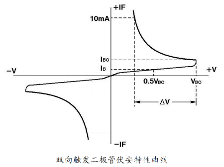
The operating principle of a trigger diode is based on the voltage–current characteristics of its internal PN junction. In the off‑state, the two terminals of the trigger diode are equivalent to two antiparallel PN junctions; because the doping concentration in the triggering layer is relatively low, its resistance is high, placing the entire device in a high‑impedance, or cutoff, state. Under these conditions, the trigger diode remains nonconductive regardless of the polarity of the applied voltage. However, when the applied voltage rises to a certain threshold—known as the trigger voltage VBO—the PN junction inside the device undergoes avalanche breakdown, causing the current to increase rapidly and driving the device into the on‑state. At this point, the voltage across the trigger diode drops sharply and stabilizes at a lower level—the on‑state voltage—while allowing a substantial current to flow.
VI. Application Examples
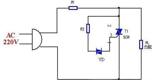
Application circuits for bidirectional trigger diodes and thyristors:
VII. Testing Methods
Measurement of forward and reverse resistance values: Using a multimeter set to the R×1k or R×10k range, measure the forward and reverse resistance of the bidirectional trigger diode. Under normal conditions, both the forward and reverse resistance should be infinite. If both the forward and reverse resistance readings are very low or zero, it indicates that the diode has broken down and is damaged.
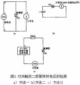
There are three methods for measuring the turn-on voltage of a bidirectional trigger diode (as shown in Figure 3):
Method One
1) Connect the megohmmeter’s positive terminal (E) and negative terminal (L) respectively to the two terminals of the bidirectional trigger diode. Use the megohmmeter to apply the breakdown voltage, and simultaneously measure the voltage using the DC voltage range of a multimeter. Then reverse the polarity of the bidirectional trigger diode and take another measurement. Compare the deviation between the two readings (typically 3–6 V). The smaller this deviation, the better the diode’s performance.
Method Two
2) First, use a multimeter to measure the mains voltage U. Then, connect the bidirectional trigger diode under test in series with the multimeter’s AC voltage measurement circuit, apply the mains voltage, and record the voltage reading U1. Next, reverse the polarity of the bidirectional trigger diode and take another reading, denoted as U2.
If the voltages U1 and U2 are equal but differ from the voltage U, this indicates that the bidirectional trigger diode exhibits good symmetry in its turn-on characteristics. If there is a significant difference between the voltages U1 and U2, it suggests that the diode’s turn-on behavior is asymmetric. If both U1 and U2 are equal to the mains voltage U, this means the diode has suffered an internal short‑circuit failure. If both U1 and U2 read 0 V, it indicates that the diode has failed due to an internal open circuit.
Method Three
3) Using a continuously adjustable DC power supply ranging from 0 to 50 V, connect the positive terminal of the power supply in series with a 20 kΩ resistor and then to one terminal of the bidirectional trigger diode. Connect the negative terminal of the power supply in series with the multimeter’s current range (set to the 1 mA scale) and then to the other terminal of the bidirectional trigger diode. Gradually increase the supply voltage; when the ammeter needle shows a noticeable deflection (greater than several tens of microamperes), it indicates that the bidirectional trigger diode has turned on. At this point, the voltage reading on the power supply represents the turn-on voltage of the bidirectional trigger diode.
Keywords:
Trigger diode,Bidirectional Trigger Diode,High-Voltage Trigger Diode,Diode,Triggering a triac,Power circuit
Contact Information
Guangdong Jiaxun Electronics Co., Ltd.
-
Address: Room 139, No. 8 Youxin Avenue, Wanjiang Subdistrict, Dongguan City, Guangdong Province
Mobile phone:18922939508
Phone:0769-2230 2199Fax: 0769-2315 8049
Email:jiaxundz@qq.com
QQ: 75836771, 343109788
Website:www.jiaxundz.com
WeChat consultation
WeChat consultation
If you have any questions, please contact us.
What services can we offer?
Copyright © 2026 Guangdong Jiaxun Electronics Co., Ltd. High-tech Enterprise: GR2019440006513Website Development: China Enterprise Dynamics Dongguan Tag


