


News
Technology transforms the world · Integrity builds the future · Leading boundless possibilities
How can the MOSFET drive current be calculated accurately?
Category:
Release Date:
2025-05-08
MOSFET drive current
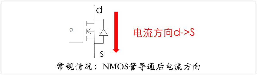
Drive current refers to the current used to control the switching process of a MOS transistor. During MOS transistor operation, sufficient charge must be injected into or removed from the gate to alter the device’s on‑state and off‑state. The magnitude of the drive current depends on factors such as the MOS transistor’s input capacitance, its switching speed, and the required switching rate in the application. A larger drive current typically enables faster switching.
MOSFET Drive Current Calculation Formula
Ig=Qg/Ton
Where: Ton = t3 - t0 ≈ td(on) + tr
td(on): The MOS transistor turn-on delay time, defined as the interval from when the gate voltage rises to 10% of its final value until the drain–source voltage (VDS) falls to 90% of its peak value.
Tr: Rise time. The time it takes for the output voltage VDS to fall from 90% of its peak value to 10% of its peak value.
Qg = (CEI) × (VGS), or Qg = Qgs + Qgd + Qod (can be found in the datasheet).
Miller-effect time (switching time) Ton/off = Qgd/Ig;
Ig=[Vb-Vgs(th)]/Rg ;
Ig: MOS gate drive current; Vb: Steady-state gate drive voltage;
Curve Estimation Method: Estimate by examining the Total Gate Charge curve in the MOSFET’s datasheet. This method is suitable for applications requiring precise control of turn-on and turn-off times.
MOSFET Drive Current Estimation
Turn on the current
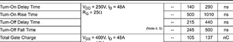
lon=Qg/Ton=Qg/Td(on)+tr, substituting the values yields lon=105 nC/(140+500) ns=164 mA
Turn-off current
loff = Qg / Toff = Qg / (Td(off) + tf); substituting the values yields loff = 105 nC / (215 + 245) ns = 228 mA.
Conclusion: The drive current only needs to be around 300 mA. Is this calculation correct? It’s important to note one crucial detail here: RG = 25 Ω. Therefore, this specification is not particularly meaningful.
How should it be calculated correctly?
The switching current is determined based on the product’s switching speed. Using the relationship I = Q/t, once we have the specific gate charge (Qg) of the MOSFET and the current‑carrying capability of our circuit, we can calculate the turn‑on time as Ton = Qg / l.
For example, for the 45N50, at Vgs = 10 V, VDS = 400 V, and Id = 48 A, Qg = 105 nC. If driven with a 1‑A gate driver, this translates into a switching speed that is approximately 105 ns faster.
Of course, this can only provide an estimate of the drive current; further testing of the MOSFET’s overshoot waveform is still required. When designing the driver circuit, a resistor of around 10 Ω is typically placed in series with the MOSFET (with parameters adjusted based on the measured waveform).
Keywords:
MOSFET drive current,Drive current,MOS transistor,Switching speed
Contact Information
Guangdong Jiaxun Electronics Co., Ltd.
-
Address: Room 139, No. 8 Youxin Avenue, Wanjiang Subdistrict, Dongguan City, Guangdong Province
Mobile phone:18922939508
Phone:0769-2230 2199Fax: 0769-2315 8049
Email:jiaxundz@qq.com
QQ: 75836771, 343109788
Website:www.jiaxundz.com
WeChat consultation
WeChat consultation
If you have any questions, please contact us.
What services can we offer?
Copyright © 2026 Guangdong Jiaxun Electronics Co., Ltd. High-tech Enterprise: GR2019440006513Website Development: China Enterprise Dynamics Dongguan Tag


