


News
Technology transforms the world · Integrity builds the future · Leading boundless possibilities
Three types of rectifier circuits help you understand why diodes can perform rectification.
Category:
Release Date:
2024-07-08
Definition of a rectifier circuit
What is a rectifier circuit? A rectifier circuit converts alternating current (AC) into direct current (DC). Typically, it consists of a transformer, a main rectification circuit, and a filtering circuit. To obtain a stable output voltage, a voltage‑regulation circuit is also required; there are many types of such circuits, which will be discussed in detail in later articles. For now, however, we will focus solely on the main rectification circuit.
Half-wave rectification
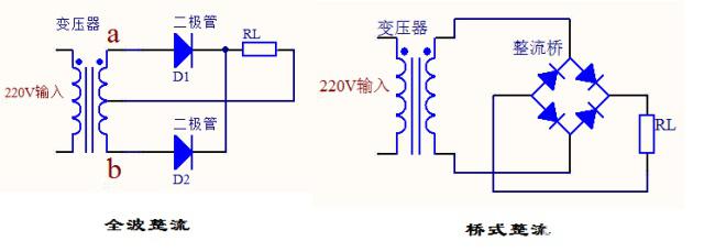
This half-wave rectifier circuit has a very simple structure, with only one component used. Diode Below is the schematic diagram of this circuit. The 220 V input is a sinusoidal AC voltage, which then passes through a transformer; after stepping down, it remains a sinusoidal AC waveform. Signal Diodes have a very characteristic property: unidirectional conductivity. If the anode voltage of a diode is higher than the cathode voltage, the diode will conduct; conversely, if the cathode voltage exceeds the anode voltage, the diode will be cut off.
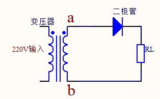
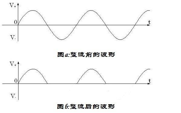
The following diagram clearly illustrates this process: in Figure a, the transformer outputs an AC voltage; when the output voltage is in the positive half‑cycle—i.e., the voltage at point a exceeds that at point b—the diode conducts, and the voltage across the load RL approximates the transformer’s output voltage, as shown in Figure b. Conversely, during the negative half‑cycle—when the voltage at point b exceeds that at point a—the diode is reverse‑biased and blocks current, so no current flows to the load; accordingly, Figure b shows one half of the waveform missing.
Full-wave rectification
In half-wave rectification, half of each cycle is lost, which clearly limits efficiency. To overcome this drawback, full-wave rectification provides a solution: it uses one additional diode compared to half-wave rectification. However, this approach also places specific requirements on the transformer, which must have a center-tapped secondary winding. The underlying principle is straightforward: it exploits the diode’s unidirectional conduction property.
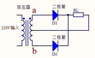
Let’s analyze this principle: when the AC voltage is in its positive half-cycle—meaning the voltage at point a is higher than that at point b—the diode D1 will conduct, while diode D2 will be reverse-biased and thus cut off. Therefore, Electric current It flows only from point A of the transformer and then passes through diode D1, Resistance RL ultimately follows the path along the transformer’s central axis.
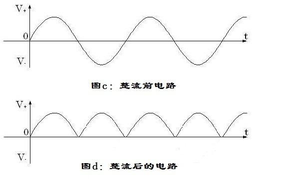
When the AC voltage is in its negative half-cycle—meaning the voltage at point b is higher than that at point a—the diode D2 becomes forward‑biased, while diode D1 is reverse‑biased. Consequently, current flows only from the transformer’s point b, through diode D2 and resistor RL, and finally back to the transformer’s center tap. This repeated cycle achieves filtering; the waveforms before and after filtering are shown in the figure below.
Bridge rectifier
Bridge rectification is somewhat more complex than the first two types, as discussed earlier. Video Zhong Ye has already explained this principle in detail; here, let’s revisit it. The schematic diagram of this rectifier circuit is as follows: a simpler bridge‑type rectifier consists of a transformer, the main… Rectifier bridge In addition to the load, commonly used rectifier bridge circuits also include filter circuits and voltage-regulation circuits; today, we will focus solely on the filtering aspect.
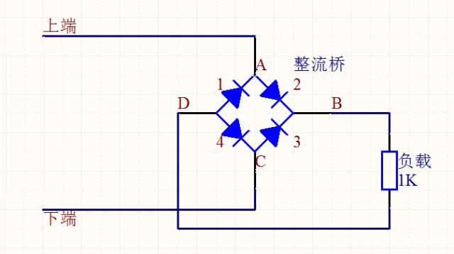
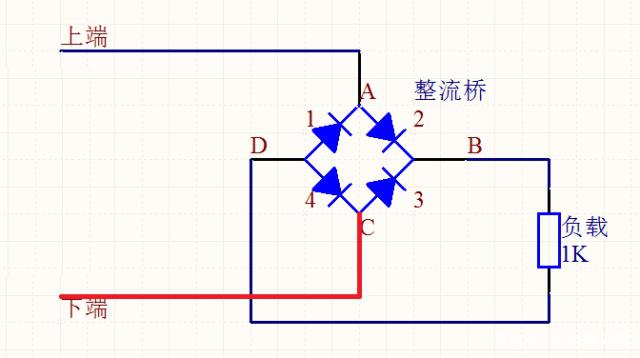
If the AC signal from the transformer is in its positive half-cycle—meaning the voltage at the top is higher than that at the bottom—under normal conditions, current flows toward point A, passing through diode 2 and then diode 1.
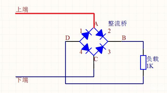
However, since the voltage at point A is higher, diode 1 is clearly in cutoff while diode 2 is conducting; consequently, current flows through diode 2, exits at point B, and then passes through the load to reach point D.
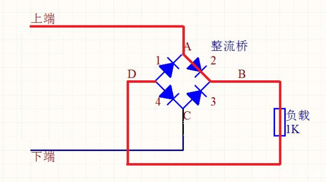
At first glance, both diode 1 and diode 4 appear to be conducting. However, current enters the rectifier bridge at point A and then passes through the load—where the voltage drops as current flows. Consequently, the voltage at point D is significantly lower than that at point A. As a result, diode 4 conducts while diode 1 remains reverse‑biased, and the current ultimately flows into the lower terminal of the transformer.
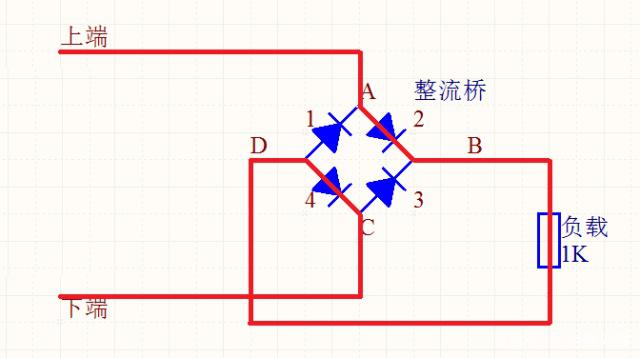
We have now completed the analysis of the positive half-cycle. Next, let us examine the negative half-cycle: when the voltage at the lower terminal of the transformer exceeds that at the upper terminal, the current, upon reaching point C, again faces two possible paths.
Similarly, because the voltage at node C is relatively high, diode 4 is in cutoff, while diode 3 is conducting. Current flows through diode 3, exiting at node B and then passing through the load to reach node D.
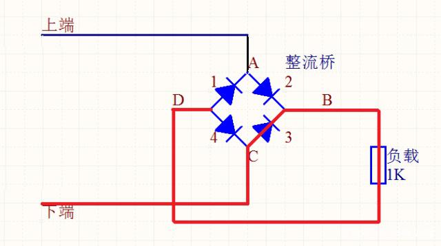
This situation is very similar to the positive half-cycle: at first glance, it might seem that both diode 1 and diode 4 are conducting. However, since current flows into the rectifier bridge from point C and then passes through the load, the voltage at point D is already significantly lower than that at point C. Consequently, diode 1 conducts while diode 4 remains reverse‑biased, and the current ultimately flows toward the upper terminal of the transformer.

If we analyze the output waveform of a bridge rectifier, we find it is almost identical to that of a full-wave rectifier. Given that the two are essentially the same, why were both rectification methods designed?
Advantages of Bridge Rectification
At first glance, full-wave rectification appears simpler than bridge rectification. However, bridge rectification offers several advantages over full-wave rectification. For instance, in terms of the transformer, full-wave rectification requires a center-tapped secondary winding, whereas bridge rectification does not have this requirement. Furthermore, when the diodes are in cutoff, the voltage across each diode in a bridge circuit is only half that of a full-wave circuit, thus placing less stringent demands on the diodes’ performance.
Keywords:
Definition of a rectifier circuit
Contact Information
Guangdong Jiaxun Electronics Co., Ltd.
-
Address: Room 139, No. 8 Youxin Avenue, Wanjiang Subdistrict, Dongguan City, Guangdong Province
Mobile phone:18922939508
Phone:0769-2230 2199Fax: 0769-2315 8049
Email:jiaxundz@qq.com
QQ: 75836771, 343109788
Website:www.jiaxundz.com
WeChat consultation
WeChat consultation
If you have any questions, please contact us.
What services can we offer?
Copyright © 2026 Guangdong Jiaxun Electronics Co., Ltd. High-tech Enterprise: GR2019440006513Website Development: China Enterprise Dynamics Dongguan Tag


