


News
Technology transforms the world · Integrity builds the future · Leading boundless possibilities
Bidirectional Trigger Diode and Thyristor Application Circuits
Category:
Release Date:
2024-05-31
1. Dimming and voltage regulation circuit
Bidirectional triggering Diode Trigger bidirectional Thyristor The dimming and voltage-regulation circuit is a typical application circuit. As shown in the figure below.
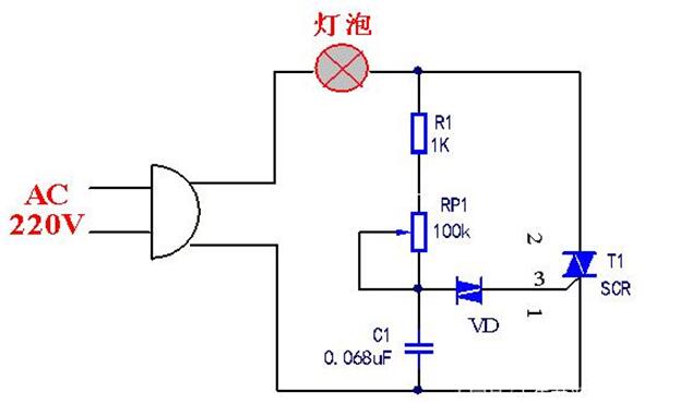
Operating process: Once the circuit is connected to the 220V AC mains supply, the AC mains power is delivered through the load. Resistance R1, Potentiometer RP1 direction Capacitor C1 keeps charging, when Capacitor When the charging voltage across capacitor C1 exceeds the trigger voltage of the bidirectional trigger diode, capacitor C discharges through the bidirectional trigger diode VD into the gate G of the triac T1, thereby triggering T1 to turn on.
It is worth noting that by adjusting the resistance of potentiometer RP1, you can control the charging rate of capacitor C1, which in turn alters the firing angle of the bidirectional thyristor and thereby changes the average current flowing through the lamp. Electric current This value enables continuous dimming and voltage regulation. Because the bidirectional trigger diode can operate under both forward and reverse voltages, a smaller capacitor can be used, reducing the power consumption of the triggering circuit. Such a circuit can be employed for dimming table lamps and stage lighting, as well as for controlling electric fans. Motor For speed regulation.
2. Overvoltage Protection circuit
As shown in the figure, this is an overvoltage protection circuit composed of a bidirectional trigger diode and a triac.
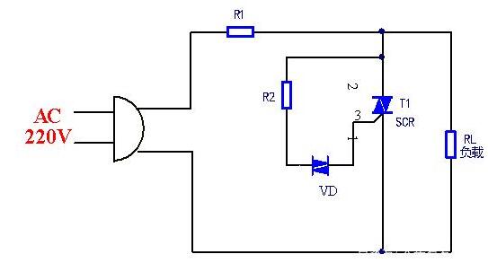
Operating principle: When the supply voltage is within its normal range, the voltage across the bidirectional trigger diode remains below its breakover voltage. Under these conditions, the diode VD does not conduct, and the triac T1 is also in the cutoff state, allowing the load RL to receive a normal output. Power supply Once the supply voltage exceeds the specified limit—i.e., when the transient voltage surpasses the breakdown voltage of the bidirectional trigger diode—the VD turns on and triggers the triac T1 to conduct as well, thereby protecting the downstream load RL from overvoltage damage.
3. Contactless Communication Switching circuit
As shown in the figure, this is a contactless AC switching circuit that can replace high‑power AC relays. Its key features include reliable operation and the absence of spark‑induced interference.
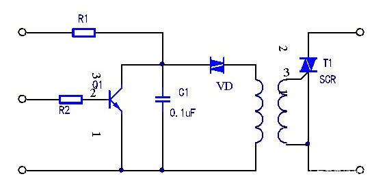
Operating process: The switching transistor Q1 controls the triggering diode to turn on, generating a trigger pulse that is then transmitted through the pulse transformer. Coupling To the gate of the bidirectional thyristor T1, which controls the thyristor’s turn-on; in this way, the trigger circuit remains electrically isolated from the main circuit. Electrical Contact.
There are many more application circuits involving bidirectional trigger diodes and thyristors, such as pulse circuits. Signal Generators, etc.
Keywords:
Bidirectional Trigger Diode,Switching circuit,Thyristor
Contact Information
Guangdong Jiaxun Electronics Co., Ltd.
-
Address: Room 139, No. 8 Youxin Avenue, Wanjiang Subdistrict, Dongguan City, Guangdong Province
Mobile phone:18922939508
Phone:0769-2230 2199Fax: 0769-2315 8049
Email:jiaxundz@qq.com
QQ: 75836771, 343109788
Website:www.jiaxundz.com
WeChat consultation
WeChat consultation
If you have any questions, please contact us.
What services can we offer?
Copyright © 2026 Guangdong Jiaxun Electronics Co., Ltd. High-tech Enterprise: GR2019440006513Website Development: China Enterprise Dynamics Dongguan Tag


